Purpose:
There are a limited number of DVD releases that have "inverted audio", the ones I know about are US released anime titles: Rurouni Kenshin DVD volume 1 (Japanese audio), first mastering; Slayers DVD set 1 (Japanese audio) and lastly, the last episode or two of Sakura Wars, dependent on the Dolby Digital decoder used (English audio). Kenshin has been fixed with a replacement program and Sakura Wars has supposedly been fixed, but that still leaves nearly 11 hours of material that drives some people crazy. A cheaper solution is to simply swap the speaker wires on the sound system, but that's not always possible and usually very inconvenient.
My intent was to show my protest of the limited quality control performed on the discs or at least the extremely limited training and experience that the checkers have in picking out basic audio problems, as well as to show that some people do notice this kind of thing, and it does screw up stereo imaging.
What is the problem and how is it solved here?
To put it simply, inversion is where one channel in a stereo system has a signal that is almost directly opposite (negative) signal to the other, and this plays havoc with how it sounds. The "inversion" affects different people and setups differently. Those using headphones may not notice the problem at all. If you use stereo speakers, you may notice that very little or no bass is heard. Those with subwoofers may find that it doesn't operate at all, as subs generally work by mixing the low frequencies of all the channels in use, and the bass of both channels cancel each other out.
Design Limitations:
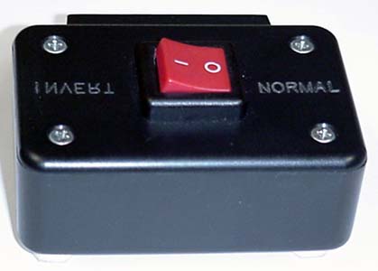
This is my first "inverter" design, kept simple, cheap and easy to build. It is passive and designed strictly for stereo-only systems or sound systems operating in stereo mode. It will not fix Dolby ProLogic processing or mono downmixing. I also do not recommend applying more than 100 watts of power through this unit or using in very high end or powerful sound systems, due to the switch rating. I highly recommend switching to and from the inversion mode with the amplifier power off! Once the switch is changed, the power can be restored. This recommendation is a safety measure intended to protect the amplifier and speakers from possible inductive spikes and other nasties.
My "beta tester" hasn't complained of any trouble, and I believe he's watched a sizable fraction of Slayers subbed with the help of this device.
This box is meant to be a short-term fix and is not intended to be a substitute for fixed DVDs, but there is no commitment from Software Sculptors as yet to fix Slayers.
Images:
Production
This box was a one-off prototype that wasn't intended for production, and I really didn't intend to make more. I intended this page to be a guide to show others how to reconstruct a similar box. I realize that not everyone has the skills or equipment to make one. The equipment to make this can easily cost $60 USD and up and it is often not worth buying the equipment for building one or two projects.
If you can't find anyone to help you, I may be able to build one for you. It would be built to the best of my ability and with the understanding that I can't be responsible for user mis-connections. If I were to make these for other people, I would charge $30 USD + shipping, $4 for Prority mail plus shipping confirmation to anywhere in the continental U.S, for anywhere else it would be a little more depending on destination. Please email me if you are interested a completed box. Otherwise if you think you can build one yourself, feel free to read on.
Construction:
The technical construction details start here. Right now I apologize that I cannot help you in your project if you decide to build this. It is up to you to read this carefully and understand what is being done here. I don't want to be mean, but right now I will state that I reserve the right to ignore questions that I feel are sufficiently answered here, as skill #1 below is the ability to read and follow directions. I will grant that I might genuinely be hard to understand at times, and if that is the case, please re-read carefully and if you still have a question, I might be able to help you.
Skills needed:
Do-it yourself capabilities and the ability to follow directions.
Soldering, wire cutting & stripping.
Drilling and cutting plastic, you will need to cut a slot in the side if you use the suggested terminal clips, or if you use binding posts of some sort, be able to drill holes for those.
Tools to engrave proper markings on the top and back plate.
Tools needed
Soldering iron and "rosin core" solder
A small phillips-style screwdriver that fits the screws.
Tools for drilling and cutting plastic.
Wire cutters and stripper.
A multimeter with a continuity or resistance check
Engraver or labeler (optional but recommended)
Shopping List:
I bought all these parts from Radio Shack. If you do not have a local Radio Shack, try to use the description to locate a suitable alternative. If you are sure you know what you are doing for your situation, nearly any part can easily be substituted for any other part with the same or better description.
| Description | Part Number | Approximate Price (US Dollars) |
| 1" x 2" x 3" Plastic Project Box | 270-1801 | $1.99 |
| 4-40 screws, 2 screws needed, 1/4" long min. | 64-3011a | $1.50 (for a 42 pack assortment) |
| 4-40 nuts (2 nuts needed) | 64-???? | $1.50 (a 30 pack) |
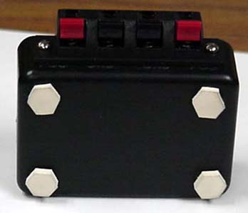
| Rubber Feet (four needed) | 64-2338 | $1.50 (27 feet with this style) |
| 10 amp double pole double throw switch (DPDT) | 275-695 | $2.79 |
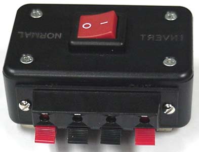
| Four Position Speaker Terminal Plate | 274-662 | $1.59 |
| ALTERNATE - Banana plug posts (4 needed), use only if you use banana plugs. | 274-661 | $2.59 / 4 pack |
| (*) 18 guage stranded wire, two colors, 1 ft. long per color | 278-567 | 4.29 (25 feet) |
Approximate Total price: $15.16 excluding taxes.
(*) One can try a larger guage wire if one desires, but the author had some difficulty soldering it to the switch properly as not all the strands would fit through the hole in the tabs.
Wiring:
The idea here is to connect the switch in a manner that one setting is wired opposite of the other.
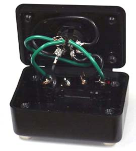
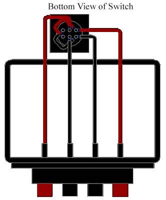
In this case, I recommend 18 guage wire as it is the easiest to solder with the given switch. The idea here is to wire the middle two switch contacts on the switch directly to what you will use as the "input" and wire the switch contacts on each corner to the opposite corner. Then on one end, wire them to the "output" speaker contacts on your box. Exactly which output wire connects to which output contact depends on how you want your box set up and how the switch works. I suggest running a continuity check before you commit to soldering the outputs. A resistance check should be done to make sure that the wire contacts have minimal resistance and to make sure that the positive wires and the negative wires never connect to each other.
I recommend checking all the connections in both switch settings to make sure that in no condition are the wrong terminals electrically connected. The picture below gives a visualization of the wiring. I hope to make a clearer drawing soon.
Final Hook-up
I am well aware that the "in" and "out" and "positive" and "negative" notations on this box are academic from an electrical standpoint. The idea here is to maintain consistency and manageability. When you hook up your home audio and video equipment, attention should be paid to being able to maintain or update your connections in the future, which is why I put the labels near the electrical contacts, which aid in determining where a wire is going. I recommend getting small label tags and noting what each cable connects to.
Notes & Apologies
I am a US citizen which has not been outside the continental US for an extended period of time, so I can't help you locate suitable places to find appropriate parts.
I am not well versed on standard Metric fastener sizes for such small screws and nuts, even so, the standard US Radio Shack doesn't carry them.
I have zero control over availability of parts.
I have zero control over how someone else uses or assembles their project, so I provide no warranty for them at all.
Due to time constraints, I might not be able to answer any or all questions regarding the design or construction, but I will try to help when I can.
Special thanks: Jon Niehof for beta testing my box on his stereo system and his defective set of Slayers.
And unfortunately, the fine print:
©2000-2001 Jeff DeMaagd
Design may be copied and used freely for non profit use only. The images, drawings, designs and descriptions are intended for experimental use only, with no warranty,express or implied. In some cases there is a chance that improper use can damage the amplifier or speakers. User is advised that user is solely responsible for any results of use. As it is an experimental design, commercial sale is highly discouraged.