Centurion 5 errata: A conversational text cycle with any name or string starting with WEND causes a "WEND without a WHILE" error. Because of this, I had to break up they name WENDY into WEN and DY to make it work. It does not seem to have problems with FOR or IF, and I have not tested other conditionals. I think our software version is 5.85.
This is to show how I fudged a faster motherboard to upgrade / repair a Centurion V control system on a Milltronics Manufacturing Partner 1 CNC machine.
Why is this important? Because I had to either replace the I/O controller or find an equal or faster motherboard with the I/O control functions built-in. From my memory, the on-board integrated I/O functions were generally not done on x86 computers until the Pentium PCIset chipsets came around.
Sure, that's nothing.
I didn't think so either. The difficulty I had was finding a motherboard that could support three true full-length ISA cards and fit in the case provided. The case was designed for AT style boards. Boards with VLB slots generally ruled themselves out because the VLB extensions would be in the way and I'd still need an I/O controller. ATX boards were about 1 to 2 cm too long to fit in the machine CPU enclosure provided. Most AT boards I have found have the CPU socket or power regulation circuitry obstructing true full-length slot capability. This meant that I needed an AT Pentium board with 3 ISA slots with all the superfluous components away from the ISA slots.
I have yet to find one. The closest I have found is the board found in these pictures. This page documents the changes I made to make it work. I had purchased a Pentium 133 computer used from a local computer store for about $80, USD.
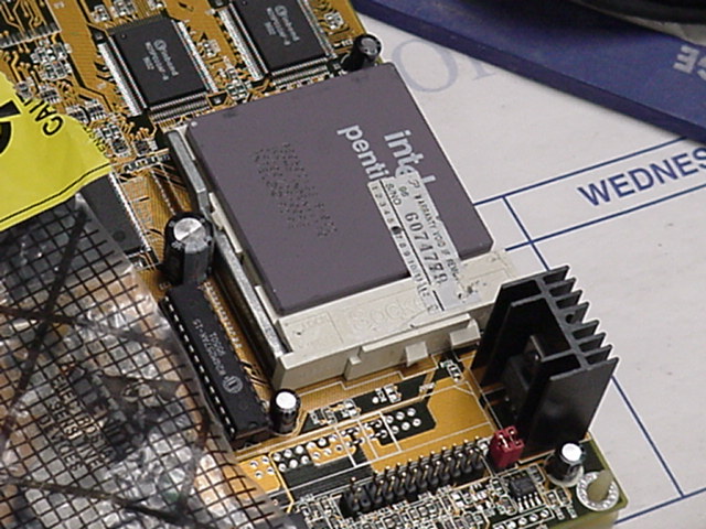
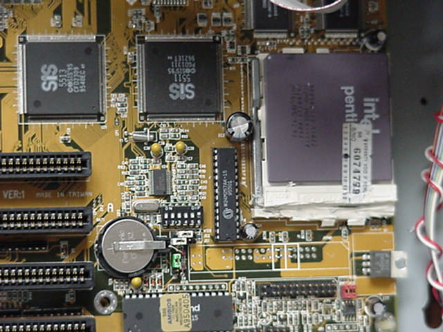
I found I had to eliminate the heat sink to get it out of the way. I might put superglue on the edges of the Pentium chip, with the heat transfer paste in the middle, as these pictures show that there is no room for the heat sink clips and that I had removed most of one snap location that the heat sink clips to. I also removed a heat sink for a three-pin device. From the code I think it's a transistor or a power regulator, I could be wrong.
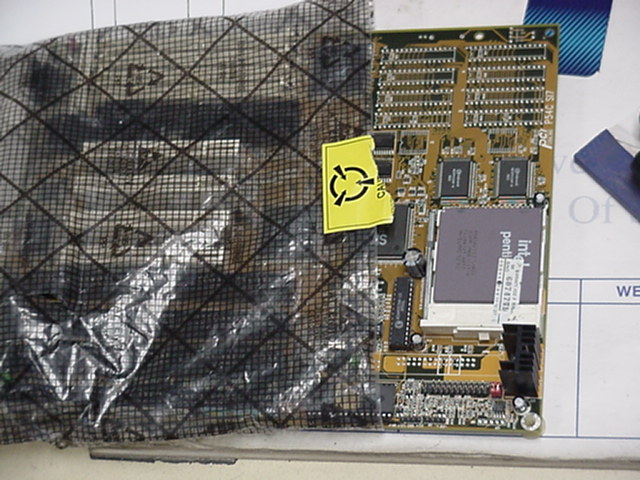
Picture 1 I put as much of the board in a static bag as possible.
Picture 2 The machine's computer case, disassembled. Note the IO card on top of the power supply is why I have to go through all of this.
Picture 3 Some of the components I had removed from the donor and the original machine computer.
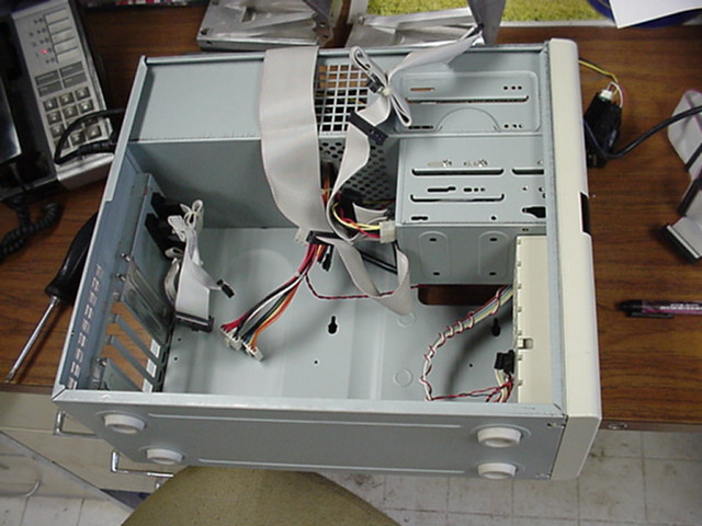
Picture 4 Empty donor computer case.
Picture 5 A close-up view of the CPU socket and surrounding area. Note the heat sink just to the right and below the CPU. This is before my changes.
Picture 13 Main board, after modification.
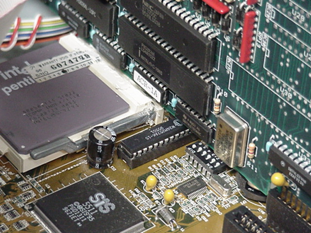
Picture 8 A close-up view of the board just after modifications.
Picture 10 A closer view of the modified area. Note the mutilations done to clear away the socket material to make room for the ISA card slot.
Picture 6 A view of the modified socket and the ISA card in it's slot. Note the close fit.
Picture 7 Overhead, ISA edge-on view. Note the lack of heat sink, the silk screen lines for it are more visible now.
Picture 11 A test-boot to see that the board still works.
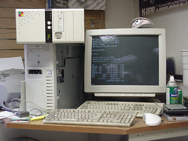
Picture 14 Installed in its final case, boot up test to make sure I didn't damage the board.
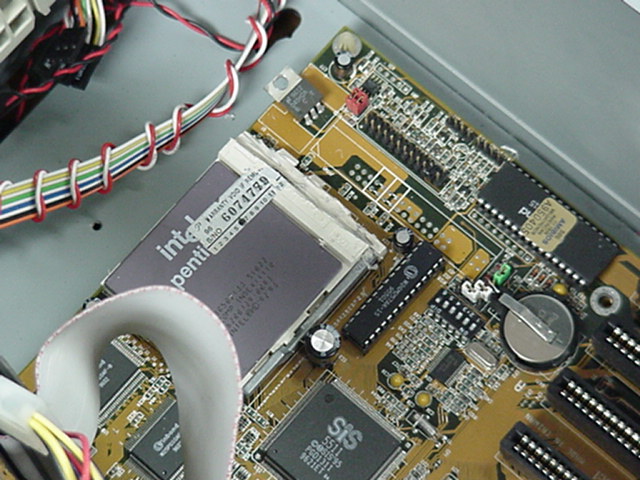
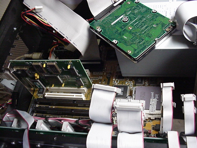
Picture 15 Internal view of the case.
You may have noticed that the picture numbers are out of order and some numbers are missing. The missing pictures show nothing that these don't, and I happended to take pictures in a certain way that required rearrangement to properly tell the story.
More to come later!
The Milltronics Manufacturing Site
My main site
©2001 Jeff DeMaagd. Mirroring and linking permission is granted so long as the ownership of this page is not hidden or usurped. All other rights reserved.